


Новое поступление

Блок питания для тестирования шагового двигателя двухфазный четырехфазный
69 136,00 руб.

02AZD810D U-WAVE-R Receiver with U-WAVEPAK | Инструменты

Brand new Magnetic base and 90 degree type mini prism with Rain hood for total station Prisms L bar GMP104 | Инструменты
US $26.50

Цифровой усилитель мощности TPA3116D2 4 канала 50 Вт x2 + 100 стерео двойной бас сабвуфер
2 376,55 руб.

Один кусок изоляции пирсинг тест клип набор Аллигатор зонды для обнаружения

Многофункциональный ПВХ 10A/20A Амперметр Тест-шнур мультиметр тест вольтметр

10PCS LM567CN DIP-8 LM567 Tone Decoder CHIP Original IC | Инструменты

Number 3 Store
Магазина Number 3 Store работает с 12.03.2023. его рейтинг составлет 74.24 баллов из 100. В избранное добавили 455 покупателя. Средний рейтинг торваров продавца 4 в продаже представленно 293 наименований товаров, успешно доставлено 416 заказов. 2667 покупателей оставили отзывы о продавце.
Характеристики
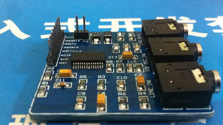
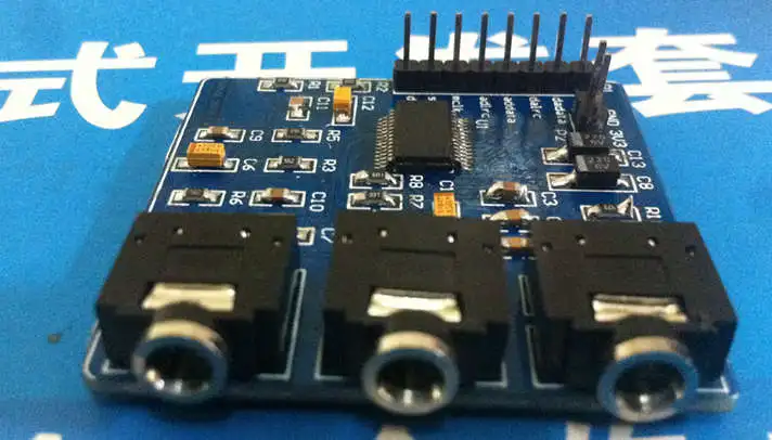
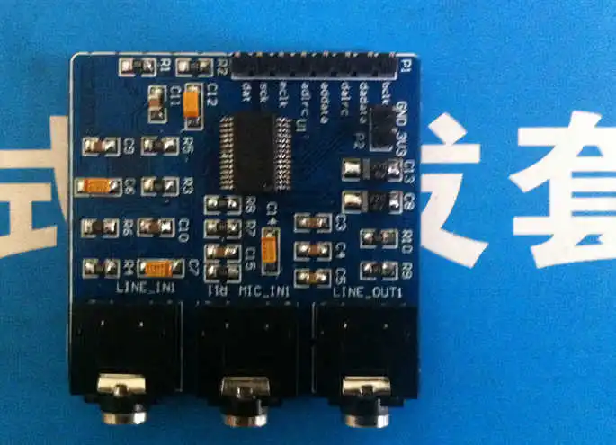
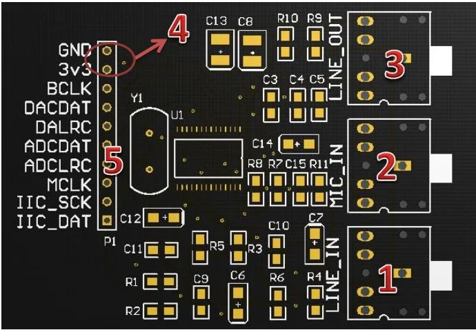
Free shipping high quality WM8731 module TLV320AIC23 audio 8731 WIFI voice raspberry pie sound card | Инструменты
История изменения цены
*Текущая стоимость уже могла изменится. Что бы узнать актуальную цену и проверить наличие товара, нажмите "Добавить в корзину"
| Месяц | Минимальная цена | Макс. стоимость | Цена |
|---|---|---|---|
| Mar-19-2026 | 0.23 руб. | 0.59 руб. | 0 руб. |
| Feb-19-2026 | 0.33 руб. | 0.52 руб. | 0 руб. |
| Jan-19-2026 | 0.66 руб. | 0.17 руб. | 0 руб. |
| Dec-19-2025 | 0.15 руб. | 0.72 руб. | 0 руб. |
| Nov-19-2025 | 0.53 руб. | 0.22 руб. | 0 руб. |
| Oct-19-2025 | 0.69 руб. | 0.2 руб. | 0 руб. |
| Sep-19-2025 | 0.52 руб. | 0.83 руб. | 0 руб. |
| Aug-19-2025 | 0.77 руб. | 0.40 руб. | 0 руб. |
| Jul-19-2025 | 0.71 руб. | 0.89 руб. | 0 руб. |
Описание товара


Processing chip WM8731 The following are the basic parameters of the chip


Смотрите так же другие товары: